Board Cluster
Board 9 introduces the Cluster Architecture paradigm. Cluster tackles down one of the most important challenge of current information technology system: The Scalability.
Very High number of concurrent users
Many concurrent users are performing Data Entry, Fetching Queries (Reports) and Procedures execution together. In this case performances can be affected during workload peak.
Cluster Load balancing smooths the case load balancing the users on several independent nodes.
Some Operations can't run in parallel on a single engine
User must perform actions , as data entry, that are necessary queued to other actions, as data-loading. The queue can affect perfromance
The different operations can be executed on different servers: a typical example is to split batch processes as Data Load or Data Load and runtime Porcess as Queries and Data Entry on different Servers.
It’s difficult to reach a central engine on a WAN
Working on World Wide WAN may be difficult in a Centralized Scenario due to unpredictable poor bandwidth : several Local Geo Server can be delivered shorting the User latency times.
THE BOARD CLUSTER SCHEMA
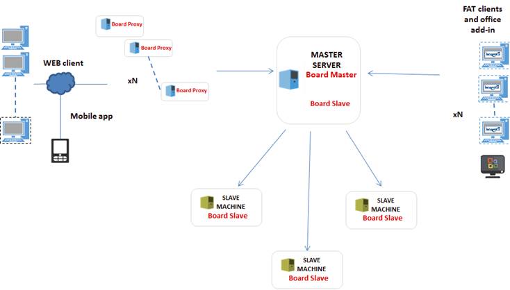
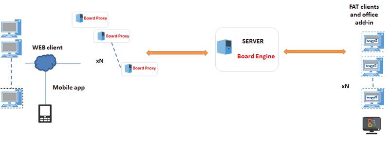
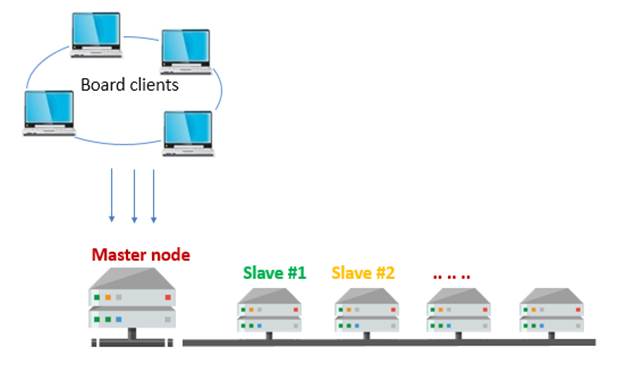
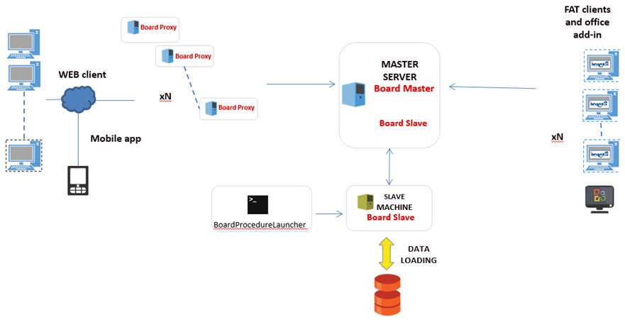
Board’s cluster technology is based on a “hub-spokes” schema where there is a main node called the “Master” node and a number of secondary nodes called the “Slaves” nodes. The Master is the single point of entry, where clients connect to. The Master node can re-direct the incoming user connection to a Slave node based on different logics (such as load-balancing depending on the user’s profile).
The Slave nodes are full Board Engine servers working as a normal Board Server instance, which receives multidimensional requests on the Board database.
When the Board Engine starts on a slave node, it must read from disk the same databases and capsules that are on the Master node. The Slave then loads the database image in memory and is ready to serve user’s requests. At start-up, the Slave nodes have the same in-memory image of the database as the Master.
When a user starts a session and connects to the Master, it will be redirected to the appropriate node, which could be either the Master node or one Slave node. From that moment on and for remainder of the session (until the user closes Board client) the communication will occur directly between the client and the Slave, the Master is no longer involved.
All user’s requests such as the queries, dataflows, datareaders, data-entry and so on, are executed locally by the BoardEngine running on the node where the user is connected. If the processing request involves some kind of update operation such as data-entry, dataflow, normalize, datareader and so on, the Slave node creates an update queue that will be transmitted to the Master, this is the “Upload queue”. A configurable timer defines the frequency, which the Slaves send their updates to the Master node. The Master node receives updates from the Slave nodes of the cluster and merges them into a “Download queue” which will be transmitted back to all the Slaves of the cluster. When a full cycle of Upload/Download is completed, all the nodes hold the same memory image of the database (therefore hold the same data).
2.2 Eventually consistent paradigm
The Board Cluster is based on the “eventually consistent” paradigm, where the different nodes of the cluster may hold different data at any given time and gradually synchronize after a cycle of Upload/Download of updates has completed. The timers driving the Upload and Download frequency can be adjusted depending on requirements and constraints. A high frequency is advisable when the data should be rapidly propagated across the nodes but generates a continuous traffic on the communication layer as opposed to a low synchronization frequency, which reduces network traffic but introduces a higher lag in the data propagation.
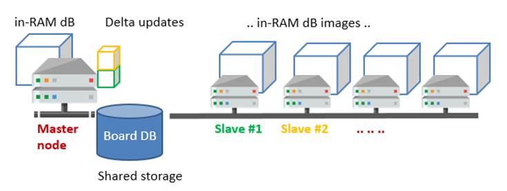
The above schema shows a cluster made of multiple Slave nodes, where each Slave sends its updates to the Master. In this schema the main Board directory is a shared drive, this allows the slaves to read the same physical storage of the database when starting. Note that immediately after the first loading in memory (server’s initialization) the storage is no more used by the Slaves, only the Master node is permitted to manage files on disk.
For performance reasons and a better isolation of the hardware processes, the Slave nodes can work using their local storage, at the condition that at the server’s initialization (i.e. when the BoardEngine service is started) the local storage is synch’ed with that of the Master. In this case also, immediately after initialization the BoardEngine will no longer manage database files on disk. The locally stored database can be considered a temporary cache to improve performance of the Slave at start-up.
2.3 Messages Synchronization
Each single node calculates multidimensional requests and the result is a compressed and ready to be sent. The message is sent to the Master as an in RAM update.
The schema below shows the usuals calculation steps:
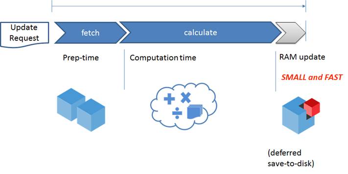
A clock triggers the synchronization between nodes. The timing is split by Download interval (Master) and Upload interval (Slave). The configuration can be done directly through the xml files (discussed later). Depending on your application nature (BI or CPM) you can decide to tune up synch parameter, according to the requirements.
The choice of the Interval is a trade-off between the wish to have the data as much updated as possible and the impact on the architecture performance that should be minimized:
• Wide intervals mean big data gaps : so you have less frequent but slow uploads
• Small intervals mean small data gaps : so you have frequent but rapid uploads
The choice should be the widest possible interval that does not affect the architecture performance significantly.
NOTE
Synchronization activity can be monitored trough the logs Error Log <BoardPath>\Dataset\Log\ClusterError_YYYYMM_SlaveName.txt
2.4 Data Storage
Board cluster is a Full In-Memory technology. Board database stored in a Disk is used only during boot-load process, after that the only interaction with the disk will be the backup procedure (SaveToDisk).
We have two settings for disk data:
- Shared: the Board path is inside a network-shared drive. Each node share the same driver
- Local: each slave has its own drive. When restarting, master database should be copied over all the local storages through copy file
In each cluster schema, the main point is to have a single point of restore. You can have the Master node in charge of backup procedure, or a dedicated Slave node.
2.5 Load Balancing
In a cluster architecture, you can decide to adopt different balancing logic based on your requirements:
Pure load balancing
Board Master Server redirects users to the various slave nodes by balancing workload (default settings). You can also decide to define a weight to each node (for example when you have hardware with different performances).
Security load balancing
Board Master Server redirect users on a particular slave node depending on its security profile (suggested when different operations are done on different nodes
Below complete list of all parameters which can be set to activate cluster system.
All update should be done after Board’s service shutdown. Restart is needed to complete update process. Each server restart, it will reload configured DB in memory. Loading time depends on DB’s size. Just only after DB loading, Board’s service will look up and running.
3.1 Xml Server config
Board cluster is a Full In-Memory technology, it does not support Hybrid mode. Each node should be configured in order to respect this guideline.
To configure your Board Engine in order to manage cluster, the parameters for server_config_v2.xml are the following:
- InMemory = “true”
- SavingPolicy = “OnServerClose”
- SaveAtMidnight = “False”
- SaveOnBoardIdle = “False”
3.2 Xml Adula Parameters
Board 9 setup installs two new xml files . Both will be installed in each server where you are going to install a new cluster node.
The xml files configuration files located into C:\Program Files\Board\Board Server:

NOTE
Each parameter update must be performed, with Board’s service off.
Master node can be activated trough <IamMaster> parameter into AdulaParamsMaster.xml. Flag should be set to true and all others parameter can be left as default ones:
TAG |
VALUE |
<IamMaster>false</IamMaster> |
Activate Master on your BoardEngine.exe |
<DownloadInterval_min>60</DownloadInterval_min> |
Set timing when Master push data on all Slaves (minutes) |
<DownloadMaxDelay_sec>10</DownloadMaxDelay_sec> |
|
<DailyHistoryLenght>0</DailyHistoryLenght> |
|
<FaultTolerance>false</FaultTolerance> |
Activate fault tolerance system |
<TransactionLogPath /> |
Specify transactional log for cluster activity. Default path: <BoardPath>\Dataset\Log\ClusterError_YYYYMM_SlaveName.txt |
|
|
|
|
Slave node can be activated through <IamSlave> parameter into AdulaParamsSlave.xml. Flag should be set to true and all others parameter can be left as default ones:
<SlavesData>
TAG |
VALUE |
<IamSlave>false</IamSlave> |
Activate Slave on your BoardEngine.exe |
<SlaveName>.. SlaveName..</SlaveName> |
String that identify node Slave name |
<SlaveAddress>..SlavePublicAddress..</SlaveAddress> |
IP or network name of the current Slave node |
<MasterAddress>..MasterPublicAddress..</MasterAddress> |
IP or network name of the current Master node |
<BasePort>9700</BasePort> |
Default communication port |
<DbSharedStoragePath>.. MasterBoardPath ..</DbSharedStoragePath> |
Empty parameter means local storage otherwise network path of the shared driver |
<OverallProfile>.. DB1 profile if any ..</OverallProfile> |
It redirects user with such profile on a given Slave |
<PerformanceIndex>100</PerformanceIndex> |
it weights the Slave Node ; it forces the Load Balancing considering the HW Size |
<UploadInterval_min>20</UploadInterval_min> |
Set timing when Slave send data to the Master node (minutes) |
<DataConsumer>true</DataConsumer> |
Specify if your node receive data from the Master node |
<DataProvider>true</DataProvider> |
Specify if your node send data to the Master node |
The second part starts from the tag <ClusteredDBs>
TAG |
VALUE |
<First>..DbName1 without extension..</First> |
Database name |
<DataMartProfile>.. DB1 profile if any ..</DataMartProfile> |
The DM_name of the Procedure Datamart Command Output |
<LocalTemporaryCubes /> |
Lists the cubes excluded from the synch process (master-slave)
|
|
|
This part can be replicated depending on the number of DBs that you have. You can decide to clusterize a subset of your DBs pool.
4 Board Cluster examples
4.1 Data loading cluster
Schema below show a possible cluster configuration whit 2 different nodes Master and Slave. The Slave node is in charge of manage all loading and extract procedures. The Master node is dedicated for all users’ activity like Data Entry, Report and so on.
The Master and Slave nodes have been configured as:
- <DataConsumer>true</DataConsumer>
- <DataProvider>true</DataProvider>
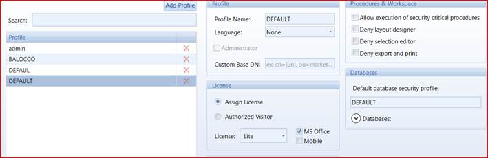
To force users dispatch to the master node, default security profile has been set as following
And in the AdulaParamSlave.xml
- <OverallProfile>DEFAULT</OverallProfile>
4.2 Geographical cluster
Schema below show a possible cluster configuration whit 4 different nodes. The Master node as central data loading center and data dispatcher to all Slaves. Each Slave nodes manage users based on belonging geographical area.
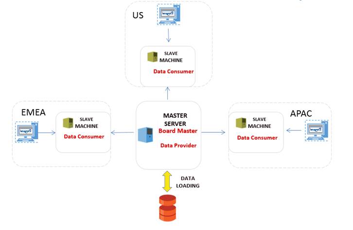
The Master node has been configured as:
- <DataConsumer>false</DataConsumer>
- <DataProvider>true</DataProvider>
The Slave nodes have been configured as:
- <DataConsumer>true</DataConsumer>
- <DataProvider>false</DataProvider>
To force users dispatch to the correct node, default security profile has been set as following in the AdulaParamSlave.xml
US SLAVE:
- <OverallProfile>US</OverallProfile>
APAC SLAVE:
- <OverallProfile>APAC</OverallProfile>
EMEA SLAVE:
- <OverallProfile>EMEA</OverallProfile>
Each default security profile should be configured according to the correct node.
4.3 Pure load balancing cluster
Schema below show a possible cluster configuration whit 4 different nodes. The Master node as a simple load balancer and Slaves dedicated to manage the workload.
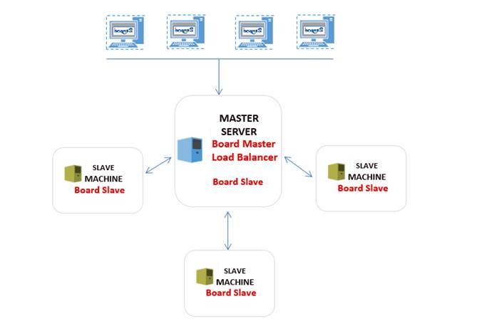
The Master and Slave nodes have been configured as:
- <DataConsumer>true</DataConsumer>
- <DataProvider>true</DataProvider>
The master will decide how to dispatch users based on load balancing logic adopted.